PROJECT – RGB LED
In this tutorial you will learn how to use an RGB LED with Arduino and create unique color combinations.
STEP – 1 : Components
Components Required:-
1. Arduino Uno
2. Breadboard
3. RGB LED
4. 3x 330Ohm resistors.
5. Wires
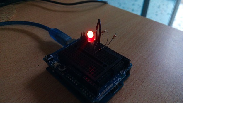
STEP – 2 : Circuit

The connections are pretty easy, see the image above with the breadboard circuit schematic.
STEP – 3 : Code
/*
RGB LED
Make an RGB LED display a rainbow of colors!
Hardware connections:
An RGB LED is actually three LEDs (red, green, and blue) in
one package. When you run them at different brightnesses,
the red, green and blue mix to form new colors.
Starting at the flattened edge of the flange on the LED,
the pins are ordered RED, COMMON, GREEN, BLUE.
Connect RED to a 330 Ohm resistor. Connect the other end
of the resistor to Arduino digital pin 9.
Connect COMMON pin to GND.
Connect GREEN to a 330 Ohm resistor. Connect the other end
of the resistor to Arduino digital pin 10.
Connect BLUE to a 330 Ohm resistor. Connect the other end
of the resistor to Arduino digital pin 11.
*/
// First we'll define the pins by name to make the sketch
// easier to follow.
// Here's a new trick: putting the word "const" in front of a
// variable indicates that this is a "constant" value that will
// never change. (You don't have to do this, but if you do, the
// Arduino will give you a friendly warning if you accidentally
// try to change the value, so it's considered good form.)
const int RED_PIN = 9;
const int GREEN_PIN = 10;
const int BLUE_PIN = 11;
// This variable controls how fast we loop through the colors.
// (Try changing this to make the fading faster or slower.)
int DISPLAY_TIME = 100; // In milliseconds
void setup()
{
// Here we'll configure the Arduino pins we're using to
// drive the LED to be outputs:
pinMode(RED_PIN, OUTPUT);
pinMode(GREEN_PIN, OUTPUT);
pinMode(BLUE_PIN, OUTPUT);
}
void loop()
{
// In this sketch, we'll start writing our own functions.
// This makes the sketch easier to follow by dividing up
// the sketch into sections, and not having everything in
// setup() or loop().
// We'll show you two ways to run the RGB LED.
// The first way is to turn the individual LEDs (red, blue,
// and green) on and off in various combinations. This gives you
// a total of eight colors (if you count "black" as a color).
// We've written a function called mainColors() that steps
// through all eight of these colors. We're only "calling" the
// function here (telling it to run). The actual function code
// is further down in the sketch.
mainColors();
// The above function turns the individual LEDs full-on and
// full-off. If you want to generate more than eight colors,
// you can do so by varying the brightness of the individual
// LEDs between full-on and full-off.
}
// Here's the mainColors() function we've written.
// This function displays the eight "main" colors that the RGB LED
// can produce. If you'd like to use one of these colors in your
// own sketch, you can copy and paste that section into your code.
void mainColors()
{
// Off (all LEDs off):
digitalWrite(RED_PIN, LOW);
digitalWrite(GREEN_PIN, LOW);
digitalWrite(BLUE_PIN, LOW);
delay(1000);
// Red (turn just the red LED on):
digitalWrite(RED_PIN, HIGH);
digitalWrite(GREEN_PIN, LOW);
digitalWrite(BLUE_PIN, LOW);
delay(1000);
// Green (turn just the green LED on):
digitalWrite(RED_PIN, LOW);
digitalWrite(GREEN_PIN, HIGH);
digitalWrite(BLUE_PIN, LOW);
delay(1000);
// Blue (turn just the blue LED on):
digitalWrite(RED_PIN, LOW);
digitalWrite(GREEN_PIN, LOW);
digitalWrite(BLUE_PIN, HIGH);
delay(1000);
// Yellow (turn red and green on):
digitalWrite(RED_PIN, HIGH);
digitalWrite(GREEN_PIN, HIGH);
digitalWrite(BLUE_PIN, LOW);
delay(1000);
// Cyan (turn green and blue on):
digitalWrite(RED_PIN, LOW);
digitalWrite(GREEN_PIN, HIGH);
digitalWrite(BLUE_PIN, HIGH);
delay(1000);
// Purple (turn red and blue on):
digitalWrite(RED_PIN, HIGH);
digitalWrite(GREEN_PIN, LOW);
digitalWrite(BLUE_PIN, HIGH);
delay(1000);
// White (turn all the LEDs on):
digitalWrite(RED_PIN, HIGH);
digitalWrite(GREEN_PIN, HIGH);
digitalWrite(BLUE_PIN, HIGH);
delay(1000);
}
/* Copy above Code and Paste in Your Arduino Sketch */
Step 4: OUTPUT!
 You have successfully completed one Arduino Project and you learned how to use an RGB LED with Arduino.
Comments
Post a Comment